
Directional relays are incorporated in the power systems sector in the field of electrical engineering to enhance the stability and reliability of electricity grids. This post is meant to focus on the condition of operation of the aforementioned handling device, breaking down all its operational aspects, many of which are unfamiliar to the layman. Understanding these aspects is critical in maximizing power system performance and averting its failure to the greatest extent possible.
What is a Directional Relay?
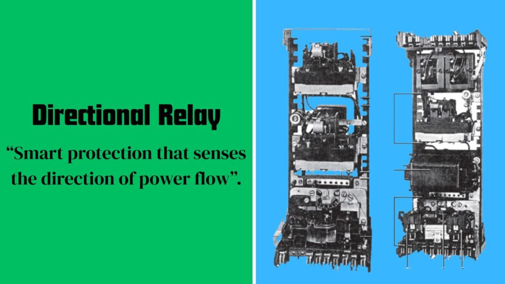
A directional relay is a type of alarm or protective relay which operates upon detecting fault occurrence in the electrical power system and determining the direction of the fault. A directional relay does not simply consider the amount of fault current as a concern when interpreting or determining the response to a fault; in addition to the amount of current, the direction of the current with respect to the positioned relay is also taken into consideration. This is particularly important in systems which have a complicated network because of the availability of multiple fault current paths.
What is the Functionality of Directional Relays?
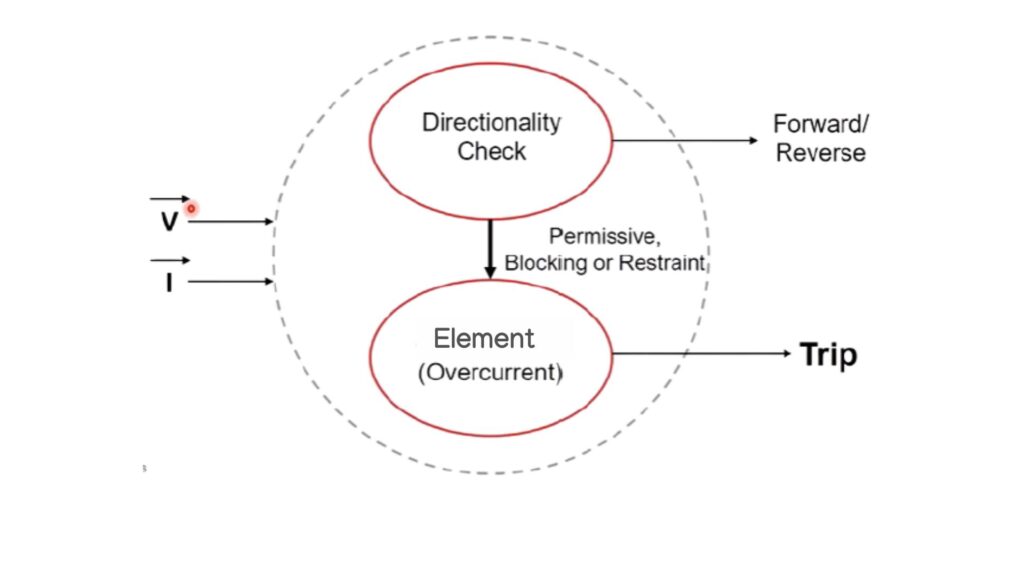
The operational mechanism of a directional relay at its finest integrates complex units and processes. Most of the time, the relay incorporates a directional element that helps in determining which way a fault current is flowing. This may consist of phase comparators whose purpose is to establish the angle formed between the current flow and the voltage. The relay also sends out trip signals to clear away the faulted section of the system when the current passes through in a direction that it deems to be a fault.
Essentials of the Effective Operation of Directional Relay
Current and voltage measurement: Successful functioning of any directional relay will always and predominantly be determined by current and voltage measurement. Continuous observation of these quantities will enhance the determination of the direction of the fault current. Any distortion or lags in measurement may lead to the inappropriate function of the relay and in turn system failure.
Correct adjustment of all the relay parameters: It is important to note that directional relays have a set of adjustment parameters which should be adhered to for the benefit of the user. This relates to the pickup value (current at which trip occurs) time delays and angle of direction sensitivity. If this has been done properly, the device should either be set up, as typically, inappropriately tripping or not tripping at all when it should be, compromising system integrity.
Arrangement of the System, Coordination Among Parameters: Large and complex power systems which comprise multiple protection devices and relays need appropriate coordination because if one protective device in the system is operated, the remaining ones would quickly operate them creating confusion. Directional relay coordination must be done with sectional relays in order to achieve selective fault clearance. This, in turn, helps to minimize the duration of outages and maintain the proper functioning of the energy system.
Internal Operation Conditions and External Conditions Affecting Use: Operational conditions of directional relay can also affect the operational efficiency of the device. Operational and installation conditions, including temperature variations, humidity and electromagnetic conditions, should be taken into account. Relays shall be placed in those conditions where the aforementioned effects are less or the relays shall be encased in protective devices for consistent functioning of the devices.
Pleasant Issues and Concerns
Like other electrical devices or equipment, directional relays have problems affecting the relay. The usual problems are improper relay configurations and settings, current and voltage transformers not operational, environmental disturbances. The maintenance and testing of the issues and problems must be undertaken and completed periodically. Help in troubleshooting and ensuring relay is working properly will be through advanced techniques utilizing diagnostic equipment such as oscillography and event recording.
An Executive Summary of Performance Optimization
Routine Calibration and Testing: It is quite important that there are regular calibration and testing of directional relays in order to sustain the efficiency and reliability. Periodic testing is done on the settings of the relay, if and when in use to ascertain that the relay is appropriately able to respond to fault conditions.
Within manufacturer suggestion compliance: Strict observance of the instructions provided by the manufacturer regarding installation, usage and maintenance and so on is required. These instructions list exactly how to set up and how to maintain the relay so as to maximize its utilization.
Availability of Enhanced Monitoring Systems: Utilizing enhanced monitoring systems can increase directional relays’ utility. Such systems give timely information and notifications that help Act even if something is amiss or could go wrong.
Conclusion
It is crucial that one comprehends the condition of operation of a directional relay. This is a key component to the reliability and effectiveness of electrical systems. By paying attention to accurate measurements, the right settings, sufficient coordination, and environmental factors in directional relays, their performance can be maximized and system failures avoided. Additionally, these increasingly ineffective devices enjoy regular servicing and decommissioning taken out of service.
Read our latest article about The Ultimate Guide to Types of Electric Motors . Any question regarding to this article please contact us.
Frequently Asked Questions (FAQs) on Directional Relay
Q1.What is a directional relay?
Further subdivided into simpler types, a directional relay is an advanced guard relay applied in electrical power systems with features for fault detection such as overcurrent or ground faults, and also determines the direction of flow of fault current with respect to the relay. The extra directional feature is important in systems where power can be fed from several sources or the configuration permits current flow to several directions. For instance in interconnected power grids or systems with looped or parallel feeders, it is important to know in what direction relative to the particular point the fault is located, that is whether it is upstream or downstream. This is accomplished by observing the voltage and current inputs of the relay and measuring their phase angle. If the angle formed between current and voltage is within a certain set value, the relay considers it as forward fault and commences the tripping of the defined circuit breaker. The enhanced selectivity for discrimination based on the direction of power flow tends to sharpen protection further. Selective isolating of the system which has the actual fault enhances system stability and continuity in the rest of the system.
Q2.Why is a directional relay used?
Directional relays are very useful and critical for advanced protection schemes within electrical networks. In radial systems with one-way power flow, non-directional relays suffice most of the time. But in today’s power systems, more so in ring systems with parallel feeders, multiple generation sources, or integrated renewable energy generation, the current flow may change due to system load, available sources, or the location of a fault. In these scenarios, the current flowing through a particular point might cause current to go from multiple directions. In the absence of direction-sensitive relays, a fault will trigger non-directional relays in several branches, leading to widespread unneeded outages. Directional relays ensure only protective devices ‘viewing’ the fault will operate. This helps in preventing cascading outages, improving fault isolation, ensuring coordinated control where only the closest protective device operates, thus enhancing system dependability and safety.
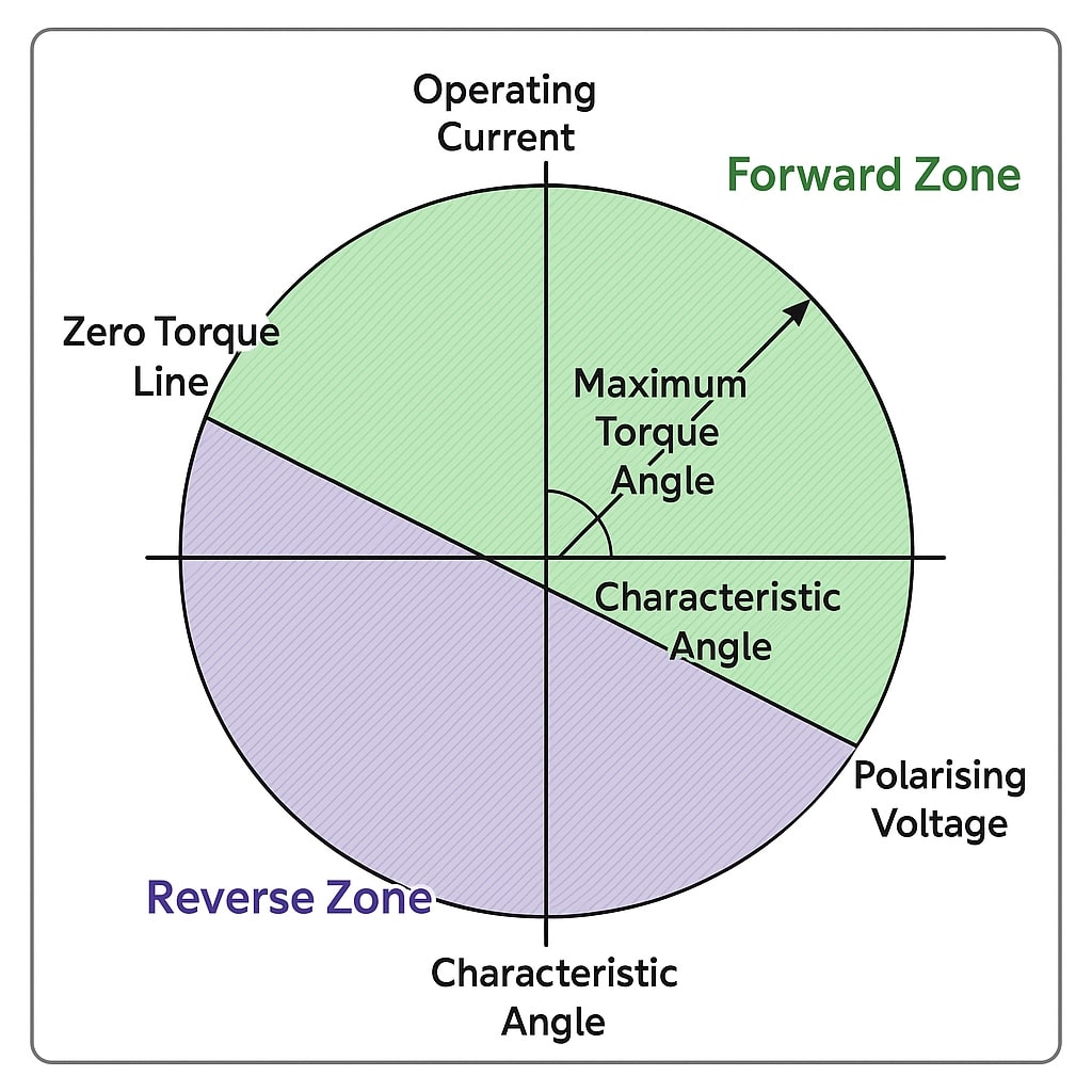
Q3.How does a directional relay work?
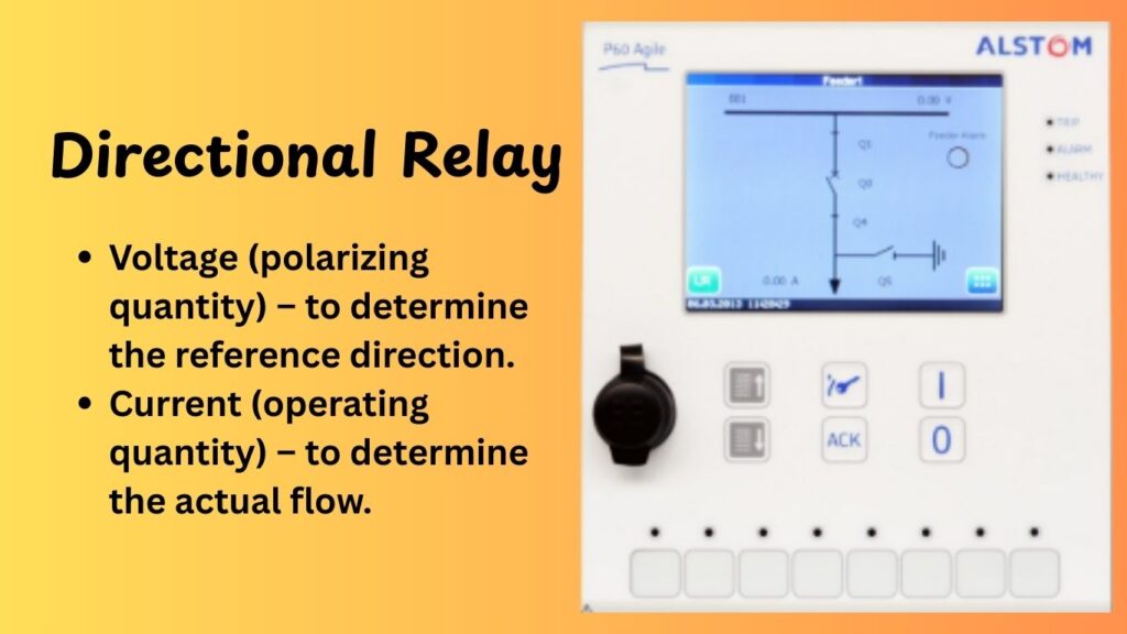
In a directional relay, the current and voltage at a chosen point within the system is compared with the phase angle. Measurement of current and voltage phase provides information regarding the flow path of power or fault current. A polarizing quantity—typically a voltage signal—is used by the relay and is served as the reference where the current to be measured is compared. For a given fault, the current vector position depends on the voltage vector position and the fault direction, thus current and voltage vector shifts. Phase comparison of the two quantities whereby the relay assesses the ‘forward’ or ‘reverse’ direction the fault based on pre-determined rules: a threshold defined by the leads and lags with which current is deemed progress or regress relative to the voltage. For example—if the fault allows the current to lead or lag the voltage within a set angular range (+90° to -90°) then the relay classifies it as forward fault. The relay only issues the trip signal under these conditions. Without satisfying these conditions, that is the bounds of the angular relationship, the trip signal will not be issued. The combination of these unique operating principles allows directional relays to effectively identify external and internal faults within sophisticated network configurations.
Q4.Where are directional relays commonly used?
Directional relays find application in multi-source interconnected and looped power systems, where currents can change with the flow due to prevailing conditions. Their most common use is in ring main units, or RMUs, where distribution lines are looped for additional resilience, and power supply can be fed from either end. They are also used widely in parallel feeder systems where two or more feeders run in parallel between substations. Directional relays resolve the issue of determining which feeder should trip in case of a fault, preventing healthy feeders from being disconnected. Another important region of application is in tie or interconnecting transmission lines where power transfer switches between different areas or utilities. In such responsibilities, directional relays for preventing reverse faults from the entire interconnected system. They are also used in industrial plants with onsite generation and utility supply to ensure proper isolation of faults on either the utility or the plant side. Their function here is equally important in renewable systems when the solar or wind farms is generating power or when the load conditions makes it necessary for power to be sent out, since the flow will be bidirectional.
Q5.What types of directional relays are there?
Each type of directional relays is configured for particular uses within the power system. The most widely used is Directional Overcurrent Relay (67). It works when the current flowing through it reaches some set value and it moves in a predetermined direction. This type is commonly found in unit protection schemes for feeders and transmission lines. Another kind is Directional Earth Fault Relay (67N or 67G). It has the capability to ground faults and is useful in systems that have impedance grounding or place a premium on ground fault discrimination. There are also Directional Power Relays which react to the primary power flow instead of the current. These are especially useful for synchronizing or load-sharing. Furthermore, Negative Sequence Directional Relays are employed to systems where there are unbalanced conditions like phase to phase, or phase to ground faults. These relays determine the direction of negative sequence components and are very useful in low fault current system. All of these variants can be constructed with electromechanical, solid-state, or digital technologies. Modern numerical relays are capable of providing multiple directional elements in a single unit which makes them more compact.
Q6.What is the difference between non-directional and directional relays?
The primary distinction between non-directional and directional relays is their responsiveness to the fault’s current flow and the current’s arc of rotation. Non-directional relays are less sophisticated appliances. They respond to the current parameter only as an input. No directional relays only respond to the current parameter only as an input and no mechanical action is performed. In this approach asserts in radial systems where kyposh/sec is one and the timer is set to a figure threshold>0. Non-directional relays non-selectively trip whenever the figure exceeds a predetermined threshold however radial systems where power flows in one direction are efficient. In contrast, intelligent non-directional relays answer using both current and voltage takes power consumption to detect fault current and the angle of current pass the threshold current must exceed set thresholds foregoing angular relationship control mechanism that define “forward” or “reverse”. These devices ensure the correct breakers trip required to maintain service and positive against uncontrolled outages. No directional relays enhance the reliability, security coordination and adaptive dyno control power systems offer responsive load variations and demands.
Q7.What inputs are required for a directional relay?
A directional relay requires two major inputs: current and voltage. The current input is supplied by the Current Transformers (CTs) which are placed on the lines to measure the line current. The voltage input is derived from the Voltage Transformers (VTs) or Potential Transformers (PTs), which always gives a smaller version of the line voltage. Both of these inputs are required to determine the current and voltage phase angle. From the angle, the relay decides the power/fault flow direction. In the case of digital relays, these signals are angularly computed internally. Relatively, the measurements must be accurate and CTs and VTs must be wired correctly in terms of polarity and phase. Wrong wiring or outright wrong polarity can trip motors falsely or make the scheme not operate for real faults, which greatly endangers the protection scheme.
Q8.What is the importance of the polarizing quantity in directional relays?
The polarizing quantity is the current or power flow reference signal enabling the current directional relay to determine the flow’s direction. Typically, the polarizing quantity used is the system voltage, but in some cases, a current or sequence component such as a negative or zero-sequence voltage can be used. With reference signals, the operating quantity (usually current) is measured to assess the angular relationship between the two. For accurate and reliable real-time measurement, the polarizing quantity must be stable, especially during system disturbances where the voltages may warp or collapse. Take, for instance, a voltage-polarized directional relay. In the case of a fault where the voltage drops to zero, the relay could lose its directional reference and malfunction. To address this challenge, some relays employ memory voltage polarization which preserves a decaying reference voltage prior to the fault for enduring directionality despite voltage loss. Thus, the ability to distinguish reverse faults from forward ones rests heavily on the reliability of the polarizing quantity.
Q9.How is the directionality of a relay determined?
The directionality of a relay is determined by the phase angle of the current and voltage in relation to the current’s position in the system power sequence. Internal subdivisions of directional relays usually include an angle comparator which determines this value and checks if it is within the defined operating zone of the relay that is usually set to a certain range of angles that determine the direction of current flow as positive. For instance, if the current flowing into the relay leads or lags the voltage within a certain angular sector,” then it will be identified as forward looking fault. Otherwise, it falls under reverse or external fault. Precise customizing capabilities of advanced digital relays are often set to this angle disabling and enabling zones which assume dual directional protection against forward and reverse faults. As for the practical aspect, correct operation of directionality will depend on the voltage and current transformers’ poles and phases supporting the relay logic. In the absence of these conditions, the device would have opportunistic directional disconnecting schemes to avert and avert disconnects when needed.
Q10.What happens if a directional relay is not set correctly?
Operational difficulties within the power system may stem from incorrect settings on a directional relay. In the case of directional angle setting errors, the relay may misinterpret the direction of a fault and there is a possibility that it does not get detected at all. Based on the situation, this might result in delayed tripping, unwanted tripping or failure to trip. Similarly, wrong polarity or phase connection of CTs or VTs would lead to incorrect assumptions about the power flow direction by the directional element. Those mistakes may cause a fault to not be isolated and allowing reckless consequences such as the escalation of destroying damages to equipment or a complete paralyzation of the system. Improper coordination of the protective relay which is upstream and downstream could disregard selectivity and cause the relays to be out of sequence resulting in the healthy sections of the network being isolated. Directional relays require thorough commissioning and testing to ensure the system is well protected.