
Within electrical systems, Current Transformers (CTs) and Potential Transformers (PTs) are equally important devices with a view of measurement and protection. In this blog post, attention is placed on the classification of CTs vs PTs, and their different attributes, including functions, uses, and defining characteristics. Understanding CT vs PT will enable you to take the proper step whether it is in the context of industrial, commercial or residential electrical projects.
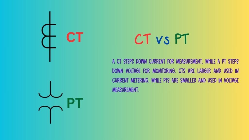
What Is a Current Transformer (CT)?
A Current Transformer (CT) is an instrument transformer appropriately employed for the measuring or monitoring electric current in a conductor. Its working principle is based on the law of electromagnetic induction, in that the primary CT circuit is placed into the circuit of the current carrying conductor in series, and the output of the secondary CT is graduated with respect to the primary. CTs are used to measure very high currents and are an important component in protective relays and metering instruments. As CTs provide lower ratio currents, they allow bulk metering of high currents which otherwise would be impossible to accomplish with measurement equipment.

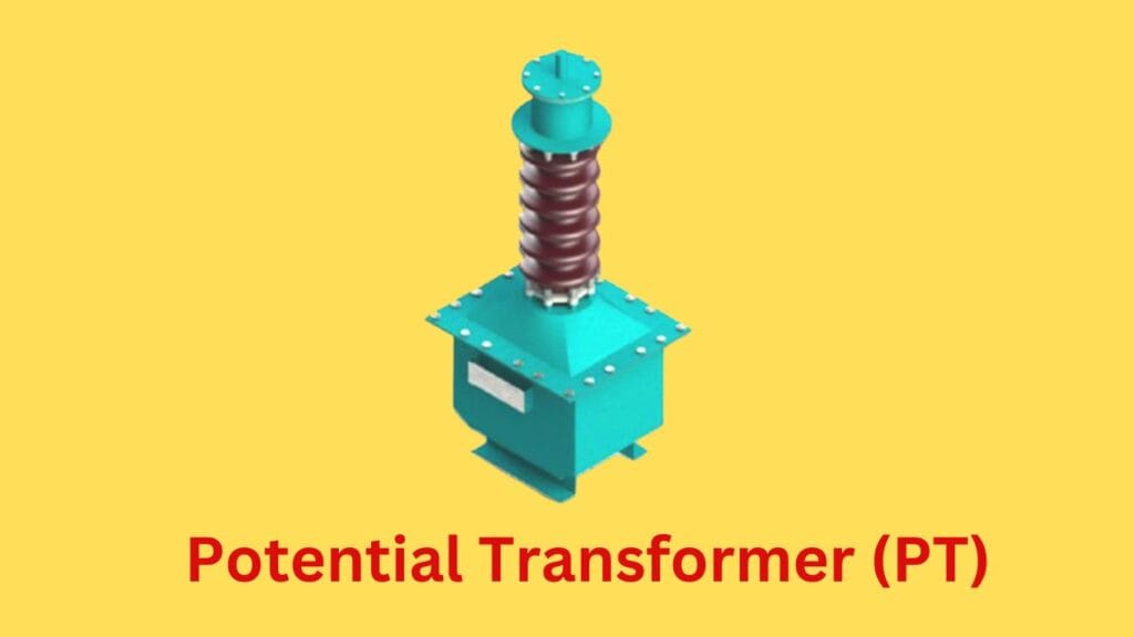
What is a Potential Transformer (PT)?
In contrast, a Potential Transformer (PT), also known as a Voltage Transformer (VT), is utilized to evaluate and assess the voltage present within an electrical system. Potential Transformers work to reduce any high voltage to a more usable value which can be handled by various instruments for measurement purposes or control and protection applications. The primary winding is connected to the high voltage side, and the secondary winding produces a lower voltage proportional to the voltage on the primary side. This rectifies the voltage for its measurement and ensures the optimal and safe operation of the system.
What do we mean by CT vs PT ratio?
CT vs PT ratio are important definitions in the field of Current Transformers CTs and Potential Transformers PTs where these parameters define the transformation from the primary to secondary coil. The CT ratio is the current in the primary coil vs current in the secondary coil expressed for example inform of a range 1000:5 in this case primary current composed of 1000 amps is converted to 5 amps in the secondary coil. This ratio is used to ascertain the correctness and scaling of the meter or protection current measurement used for any sorts of metering or protection. Likewise, the PT ratio is referred to as primary voltage e.g. 11 kV,110v means the secondary output voltage is the primary voltage of 11000 volts reduced into 110volts at the second coil. This ratio is necessary for proper voltage measurement. There are 2 beneficial aspects that hold for both ratios this is functioning of an electrical system whereby these parameters enhances the measurement system, device protection and system performance.
Key Differences Between CT vs PT
| Feature | Current Transformer (CT) | Potential Transformer (PT) |
|---|---|---|
| Function | Measures high current by stepping it down to a lower, measurable level. | Measures high voltage by stepping it down to a lower, measurable level. |
| Primary Connection | Connected in series with the power circuit. | Connected in parallel with the power circuit. |
| Secondary Connection | Provides a proportional reduced current for meters and relays. | Provides a proportional reduced voltage for meters and relays. |
| Output | Current in the secondary circuit. | Voltage in the secondary circuit. |
| Typical Ratio | 100:5A, 500:5A, etc. | 11kV/110V, 132kV/110V, etc. |
| Load Type | Connected to ammeters, protection relays, and energy meters. | Connected to voltmeters, protection relays, and energy meters. |
| Burden | Low impedance. | High impedance. |
| Accuracy Class | 5P10, 10P10 (for protection), Class 0.2, 0.5, 1.0 (for metering) | Class 0.2, 0.5, 1.0 (for metering) |
| Core Saturation | Can saturate at high currents. | Should not saturate under normal operation. |
| Primary Winding | Few turns of thick conductor. | Many turns of thin conductor. |
| Secondary Winding | Many turns of thin conductor. | Few turns of thick conductor. |
| Safety Precaution | Secondary should never be left open-circuited. | Secondary can be left open-circuited safely. |
| Use Cases | Power system protection, current measurement, relay operation. | Voltage measurement, metering, relay protection. |
CT Vs PT are essential in power systems for measurement and protection. CTs step down high currents to safer, measurable levels and are connected in series with the circuit, whereas PTs reduce high voltages and are connected in parallel. CTs provide proportional current output with low impedance, while PTs supply proportional voltage output with high impedance. CTs must never have an open secondary due to safety concerns, whereas PTs can be left open without risk. Used in ammeters, relays, and energy meters, CTs focus on current measurement, while PTs are crucial for voltage measurement and metering. CT vs PT plays a crucial role in power systems by enabling accurate current and voltage measurement, ensuring reliable operation, protection, and metering in electrical networks.
The Comparison of CT vs PT
In case CT vs PT are to be used interchangeably or the situation demands that only one of them will be suitable, primary consideration takes into account the main measurement either current or voltage. In such applications, if current measurement is needed then the most appropriate is CTs whereas in case of voltage measurement it is PTs that are justified. But, also take into account the operating voltage level and current level as well the tolerance of accuracy and what the application requires.
For this reason, for example, in a high voltage transmission system where voltage measurement is crucial, PTs are preferred. On the other hand, in the context of industries where monitoring the flow of current of machineries and equipment is important, CTs are useful. It will be beneficial to grasp the unique functioning and applications of CTs and PTs and thus help you make the right decisions and performance out of your electrical systems.
Conclusion
Finally, it could be concluded that CT vs PT are two indistinguishable parts in electrical systems which are oriented towards different but interlinked functionalities. Measuring devices termed CTs are constructed to be aimed at current, while those termed PTs focus on the measurement of voltage. Knowing the critical differences, their roles in the electrical system and other criteria on what to consider when picking map CTs over PTs enables one to achieve the desired measurement, control, and protection of the electrical systems. If you are looking for power generation or power distribution and even in its industrial engagements, then understanding these CT vs PT will assist you greatly in making the correct decisions and ensure appropriate functioning along with safety in your electrical systems.
If you require more details about CT vs PT or need assistance in locating the most suitable transformer, a qualified engineer should be contacted or a trustworthy seller visited.
Read our latest article about Features of Transformer Protection
Frequently Asked Questions (FAQs) on CT vs PT
Q1.What is the difference between CT vs PT?
A Current Transformer (CT) and a Potential Transformer (PT) are both kinds of transformers important for the electrical system. A current transformer transforms high current to a lower, measurable level whereas, A potential transformer transforms high voltage to a lower level so it can be monitored safely. CTs measure current, whereas PTs measure voltage.
Q2.Why are CT and PT used in electrical systems?
CT vs PT are applied for measurement, control, and protection in electric systems. CTs transform high currents into lower ones that can be used for measuring and relay operation while PTs transform high voltages into lower ones that can be used by monitoring and protective devices. They protect measuring devices from high-voltage circuits to ensure accuracy as well as initiate corrective actions to faults, which in turn enables safe and effective functioning of power systems.
Q3.What happens if a CT is open-circuited?
An energized Current Transformer (CT) with an open circuit can produce dangerously excessive voltage across its secondary winding. This is because CTs only work with a closed circuit in which secondary current equals primary current. An open circuit gives way to core saturation, which results in excessive voltage that can result in insulated materials being melted, electric shocks being triggered and at worst, destroying the CT. To avoid this problem, CT secondary’s must always be connected to a burden (load) or short-circuited before the disconnection.
Q4.What happens if a PT is short-circuited?
In case a Potential Transformer (PT) is short-circuited, there will be an overload of current flowing in the secondary winding which will lead to overheating, insulation damage and ultimately failure of the transformer. PTs are manufactured to provide voltage to meters and relays while taking as little power as possible. A short circuit provides a path of low resistance that can give rise to large currents, resulting in a burn out of the windings as well as serious damage. Therefore, these transformers need to be protected by fuses or circuit breakers and shorting them directly should be avoided at all times to mitigate the risks mentioned above.
Q5.How do I choose between CT vs PT for my application?
When deciding between a CT vs PT, ask yourself the following:
- Select a CT when you want to monitor current on a high voltage system. CTs transform extremely large currents (for example 1,000 amps to 5 amps) into measurably lower levels for safe metering and protection.
- Select a PT when you want to monitor voltage. PTs transform high voltage (for example 11k volts to 110 volts) to be used safely in monitoring and relay devices.
- Before choosing the correct transformer, keep in mind the accuracy class (metering or protection), burden capacity (VA rating), system voltage, or current, and safety measures needed.
Pick a CT if your application involves current monitoring, circuit protection, or relay control. If it involves voltage measurement, overvoltage metering, and protection relay then select a PT.
Q6.What are the accuracy classes of CT vs PT?
The accuracy class of CTs vs PTs are set; these classes are; 0.1, 0.5, 1.0, 5P, 10P. The higher the class the more precise they are with the measurement, the protection application depends on metering and the protection CTs can have more lenient values.
Q7.Can we use a CT instead of a PT or vice versa?
No, a CT is for current measurement and a PT is for voltage measurement. They differ in construction, functions, and even safety issues.
Q8.Why is the secondary of a CT always short-circuited?
A Current Transformer (CT) always has a short-circuited secondary to avoid excessive voltage. CTs operate in a closed circuit where secondary current equals primary current. If the CT’s secondary is open it will saturate the core which leads to extremely high voltage being induced, potentially damaging the insulation, shocking the user, or destroying the CT entirely. All CT secondary circuits have to be safely connected to a burden (i.e. a load) or shorted before they can be disconnected in order to prevent damage.
Q9.Why is the secondary of a PT always open-circuited?
The Secondary side of a Potential Transformer (PT) shall remain open ALL the time as it is designed to supply voltage, but NOT current. In the calling of Protection and metering, PTs reduce the magnitudes of High Voltages and Alarming devices or measuring instruments like voltmeters and relays are connected to the fallacious and weak looking powerful coil (secondary). The relays and voltmeters are such high impedance devices that they draw a negligible amount of current. Shorting the below described coils leads to very largeflows of current resulting in overheating and destruction of the insulation as well as possible blowing of the transformer. PTs must therefore all the time be loaded or inactive state protected by fuses.
Q10.What are the typical applications of CT vs PT?
- CTs are used in power meters, relays, and protection circuits for monitoring current flow.
- PTs are used for voltage monitoring, energy metering, and for protection in power systems.
Q11.What are the common types of CTs?
The principal types of CTs are:
- Wound CTs (primary winding is part of the circuit)
- Toroidal CTs (there is no primary winding, the conductor passes through the core)
- Bar type CTs (uses a fixed busbar as a primary winding)
Q12.What are the common types of PTs?
The known types of PTs comprise:
- Electromagnetic PTs (Standard step down transformers)
- Capacitive PTs (CVTs) (utilized for great voltage transmission lines)
- Optical PTs (Fiber optic voltage sensors)
Q13.What are the standard voltage and current ratings of CT vs PT?
CT vs PT which are also referred to as current and Voltage Transformers serve as protective devices in the power system, intended to reduce very high currents and voltages to lower values for safe measurement. The operational voltage and current ratings of CT vs PT are not alike due to their different functions. CTs are meant to measure high currents in power lines and their primary current ratings are usually between 5 A and 5000 A or higher, depending on the use. Standard CTs provide 5 A or 1 A secondary current which is meant to be appropriate for measuring instruments and protective relays. Meanwhile, PTs are meant to reduce high voltages to a lower level, usually 110 V or 120 V on the secondary side, while their primary voltage ratings can reach 11 kV, 765 kV, or even more in high-voltage transmission systems. PTs are used for accurate metering and protection, thus must ensure voltage accuracy and phase shift control within tight bounds.
When comparing CT vs PT, bear in mind the CTs measure current magnitude and are connected in a series with the circuit while PTs deal with voltage levels and are connected in parallel. Both are important in safe monitoring and automation within substations to make certain high voltage, high current circuits are monitored accurately without endangering equipment and personnel.
Q14.What is the burden of a CT vs PT?
PTs operate with transforming high voltages (11kV, 33kV, 132kV) to a lower standard voltage 110V used for metering and protection.
Q15.What is knee point voltage in CTs?
The burden refers to the connected load in volts that a CT or PT is capable of delivering while retaining the specified accuracy. Measurement errors are bound to occur if the rated burden is surpassed.
Q16.Why do CT vs PT have polarity markings?
Polarity markings indicate the correct phase relationships between primary and secondary windings which is important for accurate metering and protection coordination.
Q17.How do I test a CT or PT for accuracy?
Testing is conducted through these methods:
- CT Ratio Test (current accuracy)
- PT Ratio Test (voltage accuracy)
- Excitation Test (core saturation)
- Burden Test (loading)
Q18.Can CTs vs PTs be used for protection and metering?
Yes, CTs (current transformers) and PTs (potential transformers) can operate for both protective and metering functions, but they have specific designs for purposes assigned to them. Metering CTs and PTs, for example, have extremely high accuracy and are used for billing and monitoring purposes. During normal operating conditions, they have current and voltage measurement errors of lower accuracy class such as 0.1, 0.2, or 0.5. On the other hand, Protection CTs and PTs are meant for use during abnormal conditions of high fault current or voltages in which case they provide system safety. They tend to have greater tolerances for error, 5P or 10P, as their primary function is to activate protective devices and not provide accurate measurements.
Q19.What are the safety precautions when handling CT vs PT?
- NEVER open circuit a CT secondary while it is energized
- NEVER short circuit a PT secondary
- Make sure PTs are properly grounded
- Use manufacturer instructions for installation and maintenance
Q20.How do I select the right CT and PT for my application?
Take into account the following considerations:
- Primary & secondary ratings (current/voltage)
- Accuracy class (for metering or protection)
- Burden capacity (VA rating)
- System voltage and insulation level
Q21.What is the difference between metering and protection CT Vs PT?
Metering CTs Vs PTs are designed for accurate measurement under normal operating conditions, with high precision classes such as 0.1, 0.2, or 0.5, ensuring minimal errors in billing and monitoring. Protection CTs Vs PTs, on the other hand, are built to handle high fault currents or voltages and have accuracy classes like 5P or 10P, ensuring they trigger protective devices reliably during abnormal conditions. While metering transformers focus on precision, protection transformers prioritize system safety and fault detection.