
Transformers are a necessity in the electrical power system where electricity is transmitted and distributed in an economical manner. It is important to mitigate any operational risks that seekers are likely to face while using the transformers in order for them to be systems that can be relied upon, used effectively, and for long. In this guide, we shall discuss transformer protection comprehensively including the potential risks, the elements of protection, and the measures taken.
How Manage Transformer Protection
It is essential to note that a transformer is a machine that is not immune to some concerns that can hinder its normal running. Most common deficiencies include damage from electrical and thermal stress, breakdown in dielectric and mechanical stresses. Electric faults such as short circuits or ground faults can lead to irreversible damage to transformer components. Insulating breakages usually occur due to the age of the material or extreme weather conditions. Thermal overloads, which come about from too much current being supplied to the transformer or high temperatures surrounding it, may reduce the efficiency and working lifespan of the transformer. Mechanical stress such as vibrations or physical impacts may bring about operational faults.
Essential Features of Transformers Protection
- Circuit Breakers
- Relays
- Buchholz Relays
- Temperature Sensors
- Surge Protectors
Circuit Breakers
Circuit breakers serve a critical function in shielding the transformers from occurring electrical troubles such as overloads by means of switching it off. The devices perform this by detecting a fault in the electrical system and breaking the electrical circuit so as to protect the transformer and electric system from damage. Many circuit breakers in operation today are integrated with advanced applications such as programmability and remote observance of protection features.
Relays:
In the event of abnormal situations, protective relays stare at the electrical parameters including current and voltage as well as frequency. Once any anomaly is noticed, relays instruct the circuit breakers to disconnect the defective portion. Some of the typical relays include overcurrent relays, differential relays and distance relays, which are each used for a specified purpose.
Buchholz Relays:
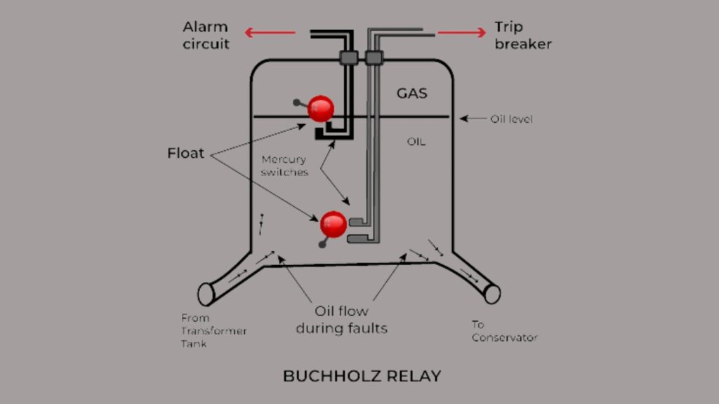
The Buchholz Relay is an essential transformer protection mechanism applied in oil transformer to assist in early detection of faults. It is a gas relay that is interposed in the pipe linking the transformer tank together with the conservator, built to monitor the presence of gas and disturbances in oil flow caused by faults within the transformer. There are two major actions from the relay: First, for minor faults such as insulation failure or overheating, gases produced by the breakdown of transformer oil collect in the upper chamber. In this case, a float is lowered signaling an alarm which notifies the operator. For more severe faults like short circuits or major arcing, there is an oil displacement in the form of an oil wave. This movement displaces a flap or lower float in the relay which immediately activates a trip signal resulting in the disconnection of the transformer from the power supply. The device overrides the power to protect the unit from further damage. Some of the components involved with the Buchholz relay are an upper float gas collection chamber which raises a flag when gas starts to surface, an oil flow detector that constantly monitors lower floats and triggers the circuit breaker when rapid oil movement is detected, a drain valve for removing and examining the gathered gas, and a transparent window which shows the amount of gas collected. This is one of the most popular in-service protective devices for power transformer protection of rating above 500 kVA. It provides an additional layer of transformer protection on top of what other devices offer on early fault diagnosis, helping to reduce system downtime while protecting the electrical system’s parts. Failure to recognize and analyze faults effectively results in severe major failures. However, by making use of the Buchholz relay these expensive repairs can be avoided, which also improves the efficiency of power distribution networks.
Temperature Sensors:
Temperature Sensors for temperature include the resistance temperature detectors as well as the thermocouples which measure the temperature of the transformer. High temperatures usually signify that there might be an insulation failure and overloads. Such sensors provide the operator with temperature information which helps reduce thermal damage for transformer protection.
Surge Protectors:
Surge protectors are devices for transformer protection that protect transformer equipment against voltage pulses due to switching or lightning. The purpose of this device is to redirect voltage from the transformer causing damage to its crucial internal parts.
Key Transformer Protection Schemes
- Differential Protection
- REF (Restricted Earth Fault) Protection
- Earth Fault Protection
- Over fluxing Protection
- Overcurrent (OC) and Short Circuit (SC) Protection
- Standby Earth Fault (SBEF) Protection
Differential Protection
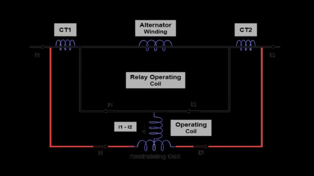
Differential protection is an intricate mechanism which ensures the safety of transformer protection by recognizing internal faults such as winding short-circuits and inter-turn faults. As a rule: currents entering and leaving the transformer are equal, as per the Kirchhoff’s law, these are 2. Comparison of current coming into and leaving the transformer is such a method. Substantial differences in these currents means fault and the relay issues a trip signal. It can be observed that this type of protection is highly, sensitive, and trip out fast when isolating faults. However, it makes a large amount of assumptions about the accuracy of the differential CTs used to monitor it, as it must be accurately set to avoid CT saturation error, or the CTs’ characteristics to be matched. Therefore, harmonic restraint is commonly used to avoid false trips.
Principle:
The protection substantially relies on the KCL which states that under normal conditions the current flowing in and out of the transformer must balance. Any deviation of such a balance would be a cause for concern.
Advantages:
- The speed of operation guarantees efficient fault clearance.
- Sensitive to internal faults, but has at least an external fault. The external fault lies outside the zone of protection.
Challenges:
- It needs suitable Current Transformers CTs to reduce the errors due to demand and supply of CTs.
- Inrush currents when magnetizing, may cause the relay to trip which means techniques based on harmonic suppression have to be implemented.
REF (Restricted Earth Fault) Protection
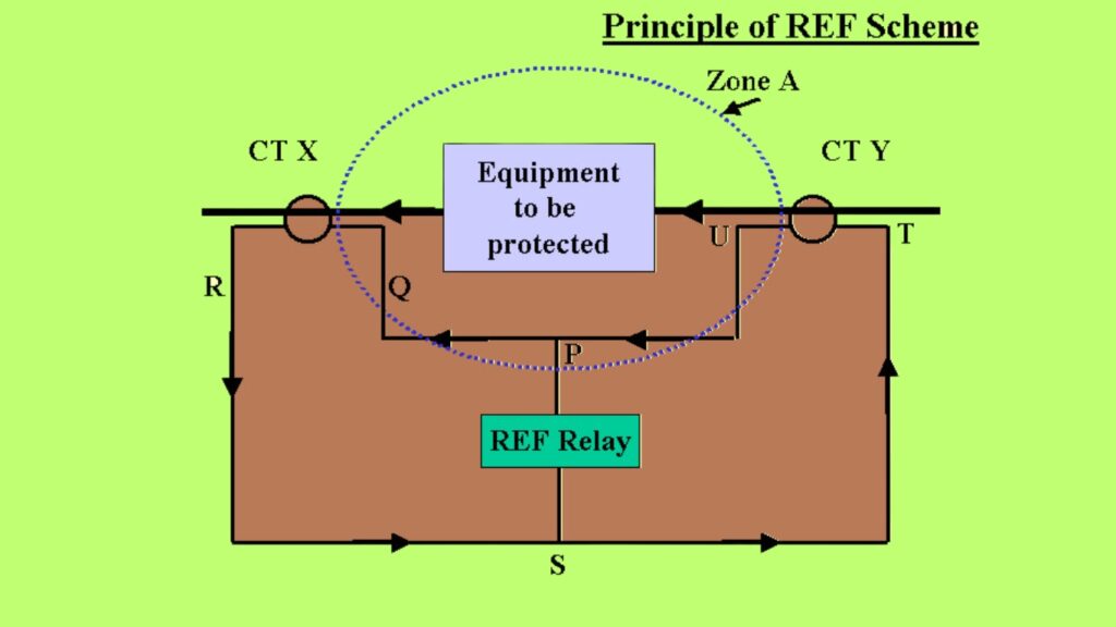
This protection is focused on the detection of earth faults within a restricted zone of the transformer, (usually located in the windings), which exist in three primary vertices- phase a, b, and c. It compares the sum of phase currents (Ph1, Ph2, Ph3) with the neutral current in the system (I0) and identifies any earth fault imbalance current. This type of protection is highly precise and such earth faults which occur but are of low-magnitude and for wider schemes these are usually difficult to zone out are easily detected. It quickly react to zones of the fault and is common with the differential protection in the case of inter-phase faults.
Principle:
By deducting the neutral current from the sum of phase currents, REF protection shows the deficiency caused by an earth fault condition.
Advantages:
- This type of transformer protection scheme is very effective against secondary earth faults that may be present in the system that has been treated with ground protection.
- The breaker takes a minimum time in operating so as to reduce the amount of damage caused.
Application:
This type of protection is used with differential protection in order to provide high quality protection against earth faults.
Earth Fault Protection

EFP or Earth Fault Protection is one such method that provides transformer protection from earth-related faults and also helps in solving the ground problem. It works by sensing unbalance which is caused by the earth fault and is represented by the unbalance current. This auxiliary protection is simple in design and is proven to be effective for most large earth faults. However, it may not be very effective for high impedance earth faults unless supplemented with zero-sequence voltage detection.
Principle:
For conservation, the number of phase currents should at all times equal to zero. If there is a net current left flowing, a fault has most likely happened.
Application:
- It has the advantages of being easily implemented.
- It is also capable of successfully identifying large earth faults.
Challenges:
It has very low tolerance levels towards high-impedance earth faults unless it is supplemented by other protection methods like detection of zero-sequence voltages.
Over fluxing Protection
Over fluxing Protection also seems to give similar protection but this seems to protect the flux of the transformer core and anything else that could harm it during something like a large magnetic field when there is an overvolts per frequency (V/f) ratio that exceeds the maximum expected value for that transformer. This protection keeps track of V/f and cuts off transformer circuits when the values cross certain limits. It protects the transformer from partial melting and some core mechanical load balancing due to maintaining the transformer’s operational range. It is very important to take special care and set the ratios exactly before adjusting them to ensure potential over fluxing is avoided without disrupting normal flux.
Principle:
The key to preventing Over fluxing is measuring the V/f ratio. If the ratio rises over the metrics set by the relay, a trip signal is tripped.
Advantages:
- Minimizes the risk of melting and mechanical deformation of the core.
- Ensures that the transformer does not get damaged over a long time or in abnormal conditions.
Challenges:
- Close supervision of the V/f ratio parameters is necessary to ensure that the transformer does not overheat.
- Special attention has to be paid in the initial setting phase to make sure that the over fluxing does not occur due to minor disturbances.
Overcurrent (OC) and Short Circuit (SC) Protection
Overcurrent and short circuit protection devices measure overcurrent and extreme overloads which are the results of a fault. Load overcurrent devices prevent overloading of the circuit by cutting the circuit off daily if the load current measures over a set limit. This is crucial for ensuring that the winding does not overheat. Short Circuit on the other hand aims at cutting the power supply to portions of the circuit experiencing great stress and fault in order to avoid unwanted damage to the circuit. It essentially scans all the transformers for short circuit and bus bar faults. Both protection devices ensure that any non-normal conditions do not interrupt the operations and do not cause severe damages to the equipment.
Overcurrent Protection:
Principle:
This system controls the transformer when the load current goes beyond the set limit for a long time.
Advantages:
It can be useful in extending the running time of the load in situations of continuous overload conditions where the windings might be heated up.
Short Circuit Protection:
Principle:
This operation is able to recognize catastrophic fault currents and disconnect the transformer without delay from the circuit
Standby Earth Fault (SBEF) Protection
Standby Earth Fault transformer protection is more of an over protection which is a backup of the main earth fault protection. It can pick up EOF available on the n/earth or ground connection of other substations which are not situated in the primer protective zone region of the circuit. This type of protection is ideal as it increases chances of redundancy. SBEF is also adjustable so that it can work with other devices without capturing the wrong signals and is very common in large substations and in transformers that cater a huge load for example.
Principle:
Uses residual current at the neutral or ground connection to sense fault conditions.
Advantages:
- Provides redundancy and improved overall protection.
- Can be time delayed with other protections to prevent nuisance tripping.
- Application: Commonly deployed in big substations and vital transformer locations.
Best Practices for Transformer Protection
Regular Maintenance and Inspections:
Regular maintenance and inspections refer to the precautionary measures that one takes in order to identify an issue before it occurs. Some of such works include checking insulation resistance, cooling systems and running of the protective devices. Proper maintenance ensures that transformers operate under their designed parameters and for a long duration.
Monitoring Systems:
The transformer protection can be improved through the use of advanced monitoring systems, where data on various operating conditions are generated in on-time basis. These systems can comprise of online diagnostics, predictive maintenance tools, and remote monitoring capabilities. In anticipation of problems, operators can analyze trends and look for anomalies and then take preventative action.
Load Management:
It is important to provide an optimum management of the load to avoid thermal overloads and consequent performance degradation of the transformers. This includes load sharing between the transformers so that no single transformer is operated beyond its design limits and load shedding schemes whenever there is peak load demand.
Environmental Protection:
It is just as important to safeguard the transformers from moisture, dust, and temperature as it is to ensure their proper functionality. Structural and heat dissipation means should also be high enough to give protection against environmental challenges if not add up to blocking impurities.
Training and Safety Protocols:
It is of great importance that the staff trained in the operation of the transformers, including all aspects of transformer protection and safety adheres to the rules for effective operation and maintenance of the transformer. Instruction on the use of structural protection methods, tolerance of electrical isolation, response to atypical situations, and treatment practices.
The Importance of Transformer Protection
When an effective transformer protection is adhered to not only is destruction avoided and reliability guaranteed but benefits are brought even to the entire electrical power system. With the deployment of effective protective measures, downtimes will be reduced, maintenance cost will go down, and both personnel and equipment will be more secure when operating hazards will be less.
Conclusion
Transformer protection is a detailed process revolving around the possible threats to the equipment, protective devices that are going to be used, and the practices that are to be followed. Operators can take the necessary steps and risks in order to promote efficient and effective operation of transformer equipment, in which case the electrical power system will be well protected, and the service life of the transformers will be enhanced throughout their usefulness period. Adopting and implementing such advanced transformer protection facilities not only improves system availability but also effectiveness and safety of operations. For further details on transformer protection including current developments in protective devices, reach out to professionals in the field or consider relevant literature.
Read our latest article about Magneto Motive Force (MMF): The Ultimate Guide to Electromagnetic Efficiency
FAQs
Q1.What is transformer protection?
Transformer Protection is the set of systems, devices or methods which are aimed at minimizing the risks of damage to transformers from overcurrent’s, and mechanical and environmental factors. These strategies guarantee reliable and sound operations of these transformers which are important equipment in the electrical networks of transmission and distribution power systems.
Q2.Why is transformer protection important?
Transformers are critical in the electrical power system in that they either raise or lower voltages in a bid to enhance efficiency during transmission and distribution. In the absence of adequate safeguards in place, a number of faults are likely to compromise the integrity of the transformers rendering them unable to perform their functions which would result into a loss of a great deal of money together with equipment destruction and sometimes could even pose a danger to life. Even in cases where such faults are taken care of, a longer life cycle, higher reliability and better functionality of the whole power system can be expected.
Q3.What are the common types of transformer faults?
There are several faults that a transformer could develop that may compromise its ability to perform its functions. For instance, short circuits cause an abnormal increase in the current, overloading where the transformer is used above its threshold limit, changes in transformer insulation materials due to time or heat, and earth faults where current passes through the earth. It is essential for a system to remain stable that such faults are comprehended and solved as soon as possible.
Q4.What are the primary methods of transformer protection?
Various methods are used to transformer protection against any faults. The overcurrent protection provides safeguarding from the damage by limiting us with the maximum potential. The differential protects from internal damage, as it tries to retain the equilibrium between the power input and outputs, if not, then there is wracking within. The earth fault protection cuts off the power supply whenever any wiring attach to the earth in electrical terms. Adding on, there brass temperature gauges as thermal overload protection, which does not let the temperature rise above a certain range that might cause damage.
Q5.What is differential transformer protection?
Differential transformer protection is one of the most considerable techniques in transformer engineering, as it allows them to detect any internal mismatches that may occur. What it does is that it limits the amount of current being transported in or out of the transformer, if there is an imbalance, it means damage has occurred such as winding short circuit or breakdown of insulators. It is extremely beneficial as it is very sensitive as well as quick to detect any faults meaning that the power system has a much higher chance of retaining its integrity.
Q6.How does Buchholz relay work in transformer protection?
Buchholz relay is a device that is useful in oil filled transformers as it detects gas accumulation. Gas Accumulation is caused due to accumulation of gas as a result of internal transformer faults. Once the Buchholz relay activates, it opens the circuit breakers, thus switching the transformer off to ensure that it does not get damaged any further.
Q7.What is the role of surge protection for transformers?
Transformers can remain unaffected under such extreme conditions because surge protection prevents voltage spikes during lightning strikes, during grid switching or under other parameters. Such spikes may impair the insulations and sulfate transformer liquid employed in the transformers. The safety of transformers and their lifespan is ensured with the help of surge protection devices like arresters, which send excess voltage to the ground.
Q8.How can transformer protection systems be tested?
Testing transformer protection systems on a regular basis is quite necessary for verifying their adequacy. This includes relay testing of the fault locating device, leakage testing of insulation resistance determining the resistance value, and thermal imaging aimed to locate elevated temperature on equipment surfaces. Oil sampling and analysis can also help if there is a notable amount of contamination or gas formation, these are signs of damage to the transformer.
Q9.How often should transformer protection systems be inspected?
The frequency of inspections will depend on the use and criticality of the transformer. As a rule of thumb, A discharge transformer protection system should be checked on a yearly basis. However, in some critical applications or high load regions of business, the frequency should be quarterly or even monthly. This early detection of malfunctioning and rectifying it assures that small faults do not develop into serious issues.
Q10.What are the signs of a failing transformer?
Often, a buzz or hum can be heard from the transformer, this is combined with overheating from too much load or issues with cooling, which lead to oil leaking from seals that have worn out, hence these can be taken as indicators that the transformer is on the verge of failing or has failed. However, there are a few substrates that can be used to identify this change as well, such as a significant discoloration of transformer oil, or devices going into a tripped state more frequently.
Q11.What is numerical transformer protection?
A microprocessor based system that deploys the use of numerical protection is the use of substation automation systems with a more specific focus on the transformers. These numerically controlled devices facilitate fault detection alongside more advanced features such as onboard memory, real time processing, as well as remote diagnostics. All in all, these systems are superior to the previous electro-mechanical systems in terms of their accuracy and diversity.
Q12.How do modern transformers incorporate smart protection systems?
Foundation of smart protection is built upon AI and IoT technology which has proved to be the best in the market with seamless smart protection. Having access to real time data allows the users to control the loner tools and lead to fewer interruptions. AI proves to make things even easier with its automatic alerts and remote assisted diagnosis.
Q13.Can renewable energy systems use traditional transformer protection?
The majority of transformers’ protection and control units can be inherited in renewable energy systems but with some modification and customization. This is because renewable sources like wind and solar are variable and produce discontinuous power flows and protection systems of such sources differ from conventional systems protecting synchronous machines.
Q14.What standards govern transformer protection systems?
It is the International and Europe standards set include IEC 60076 for power transformers and IEEE C57 for general transformer practices that govern transformer protection systems. These standards ensure that protection systems are designed, used and tested in accordance to set safety and performance benchmarks.
Q15.What role does transformer cooling play in protection?
Transformers over heating is among the major causes of failure which has a simple remedy of cooling that every transformer requires cooling. Cooling systems can either be Oil, Air or Water, Depending on the type of transformer. The purpose of the above is to remove excess heat that is produced during its operation. Lowering the temperature has common practice in thermal stress and increases a transformer’s life further.